 How to intercept the hue switch?
I would like to intercept a hue switch button to turn on a light under knx? how can I do?

 Z-wave - Leviton dimmer #DZ6HD status not updated in UI
Hello guys,
I have added to the Z-wave node the Leviton dimmer DZ6HD. It responds to the commands initiated from UI to toggle and dimmer the lights connected to the switch. If I operate manually the switch the status does't get updated in bOS. Have any idea why it doesn't work?
Thank you,
Calin

 Z-Wave gateway IP communication
I have a Z-Wave controller i have to communicate with ip.
When i add Z-wave , there is no options for ip, but the help guide have.
What are i'm doing wrong?
Help guide:

 Are Solar Edge inverters being supported?
Hello,
I was wandering if inverters from Solar Edge are being support in same way as SMA inverters are supported.
See link to website: https://www.solaredge.com/us/products/pv-monitoring#/
Regards,
Fred

 d-link camera
I have a D-Link camera DCS-930L, I know is a lame camera, but I'm not able connect to the camera, I'm using this link http://admin:admin@192.168.220.103/mjpeg.cgi with VLC client and works, with Chrome too works and with FireFox too.
BOS Config always set to false Online and Streaming vars.
Any idea?.
Camera config
Username:admin
Password:admin
IP:192.168.220.103
Video Size:640:480
JPEG source:--
Refresh time:1000 (default)
Mode:Direct (I have tried all modes)
WanIP:--
MJPEG Source: mjpeg.cgi (tried winth slash before name)
MPEG Source:-- (too tried with video.cgi
Best Regards

 Camera configurator bad login
Hello. I ran into problem with onvif configurator in bOS. I click on configurator and see all camera but if I try to add it I enter Name and Password and get bad login error. And name and password work on other onvif program. Please help.

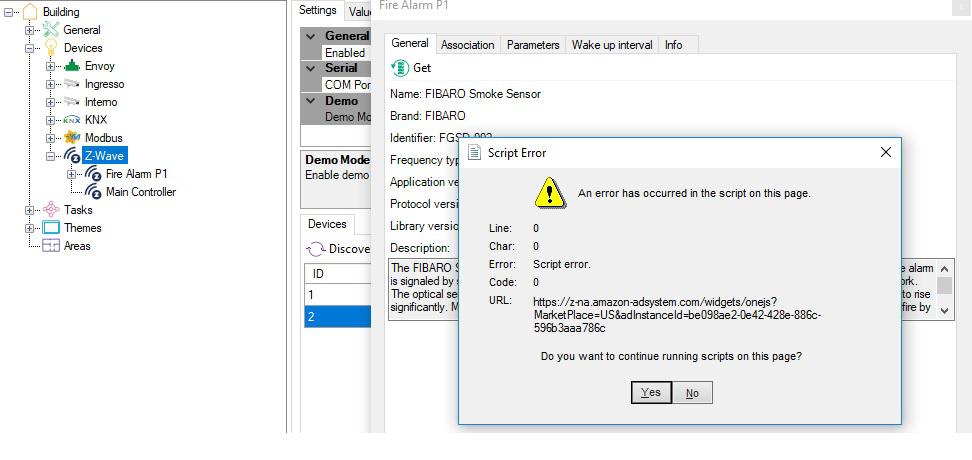
 Z-Wave Bug
Dears
every time I open the setting proprieties of eth included Z Wave device I got the following error message:

In my case the integrated device used is the Fibaro ZWave plus smoke sensor. Can you fix it please?
Regards
Marco

 MCO HOME RELAYS
MCO home relays are getting added in jigsaw z wave but the issue is with the feedback ( status ). We have used jigsaw z wave and also the UZB stick
but still no success. The same stick over any other server or computer gives feedback for MCO home relays. Can anyone please comment ?

 MODBUS WITH PRODUAL HLS 44 Thermostat
I am trying to integrate Modbus Thermostat ( Produal HLS 44 ) with Jigsaw Z wave via RS 485 ( RTU ). The register details are mentioned below :-
Holding Register Address 1 ( 40001 ) = FAN SPEED CONTROL WRITE
Holding Register Address 2 ( 40002 ) = SET POINT WRITE
Input Register Address 18 ( 30018 ) = SET POINT BY USER
Input Register Address 19 ( 30019 ) = FAN CONTROL BY USER
Those Address were verified using MODSCAN 32 and found to be correct.
Now in jigsaw, the scenario is different. The setup was :-
ACTUALLY ADDRESS 18 IS FOR SET POINT BUT I AM GETTING THE SET POINT IN ADDRESS 17 ( 18 - 1 )
SIMILARLY ADDRESS 19 IS FOR FAN SPEED AND I AM GETTING IN ADDRESS 18 ( 19 - 1)
So what we have seen is for input register, we need to deduct -1 with the address mentioned in datasheet.
REGARDING THE HOLDING REGISTER 1 AND 2, IT IS NOT WORKING. I AM ABLE TO GET DATA FROM INPUT REGISTER BY DEDUCTING THE ADDRESS BY 1. BUT I AM NOT ABLE TO WRITE ANYTHING IN HOLDING REGISTER.
ALSO THE VALUE FROM INPUT REGISTER IS LIKE 280, 275, 220. WE NEED THE VALUE LIKE 28, 27.5, 22 ( divided by 10 ).
CAN YOU PLEASE SUPPORT ?
Customer support service by UserEcho


